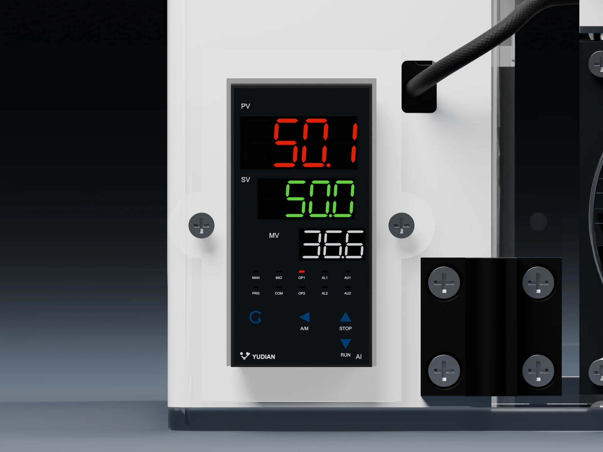
Set and read temperature
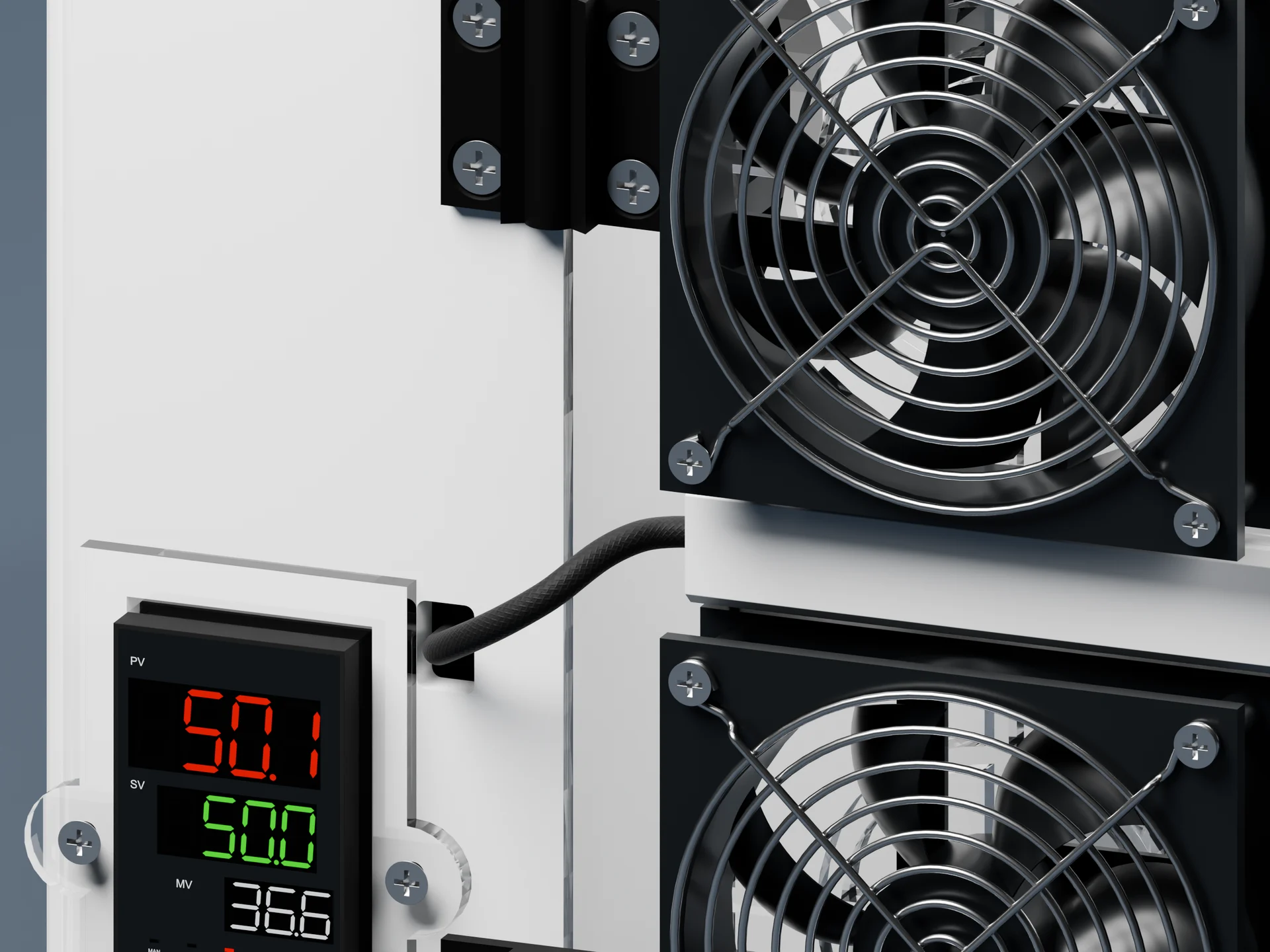
The controller presents measured and set values. Display examples are not evidence of overall chamber accuracy.
DENSERACK TEST EQUIPMENT
Controlled air-temperature conditions for electronics testing.
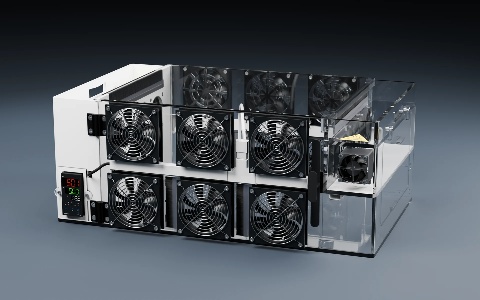
Electric heating, circulating airflow and PID control. Two sizes for motherboard, server and electronics test setups.
No active cooling. Achievable temperatures depend on ambient conditions, device heat load and test setup. Confirm the operating range for your configuration.
01 / FIND YOUR FIT
Start with equipment fit, then review heat load, cable routing and access.
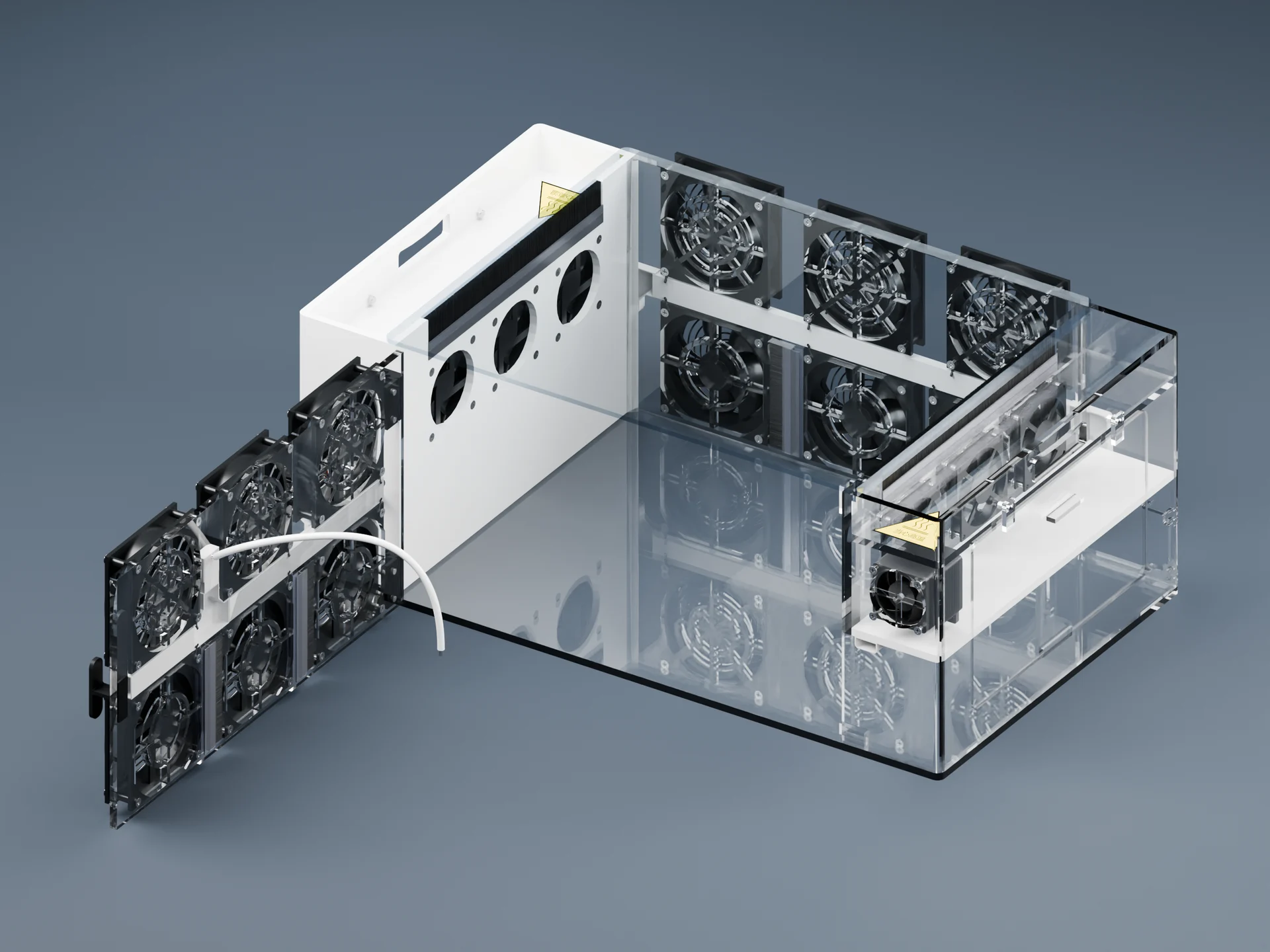
DR-WKX-L-G1
For larger systems and laboratory setups, with the power inlet and main switch at the rear.
Confirm overall dimensions, usable space and loading conditions when selecting a model.
Swipe to compare. Item labels stay visible.
| Item | Large | Small |
|---|---|---|
| Part Number | DR-WKX-L-G1 | DR-WKX-S-G1 |
| Best for | Larger systems and laboratory setups | Board-level and benchtop setups |
| Power inlet & main switch | Rear | Front |
| Control Method | PID control | PID control |
| Temperature Range | Confirm for ambient conditions and heat load | Confirm for ambient conditions and heat load |
| Overall / usable dimensions | Confirm for your equipment | Confirm for your equipment |
02 / BUILT AROUND THE TEST
Explore the controls, connections and cable routing in the product views.
The controller presents measured and set values. Display examples are not evidence of overall chamber accuracy.
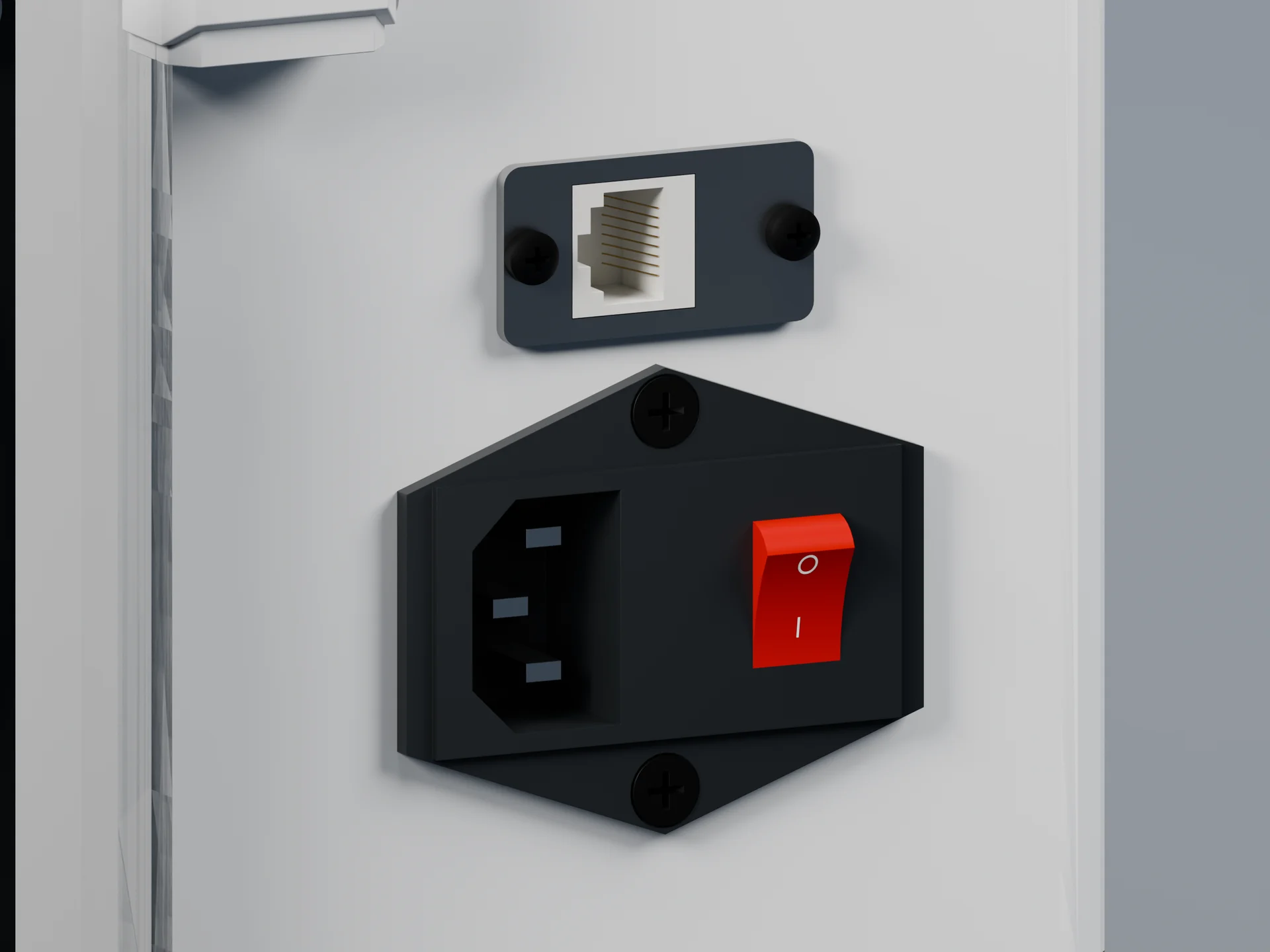
Rear-mounted on Large and front-mounted on Small. Confirm the model-specific supply and protection requirements.
Route equipment and measurement cables without obstructing the door, cover or airflow.
Sensor feedback regulates heater output while fans circulate the air.
Control relationship only, not a measured airflow or temperature map
The display reports air temperature at the sensor, not device temperature. Measure cooler intake and surfaces separately; use a suitable method to measure or estimate junction temperature.
03 / APPLICATIONS
Observe fan response and system behavior. Measure cooler intake and component temperatures independently.
Check operation under agreed air-temperature conditions, with equipment dimensions and continuous heat load reviewed first.
Observe board-level operation and thermal response in a controlled heated-air environment.
04 / PRODUCT VIEWS
Explore the enclosure, controls, cable routing and access views. Choose a model and enlarge an image. Setup illustrations include their limitations; confirm the supplied configuration with your order.
Large · Front three-quarter view
01 / 13Small-model presentation video; review the current product views for appearance and configuration.
DR-WKX-S-G1 · 00:36Large-model presentation video; review the current product views for appearance and configuration.
DR-WKX-L-G1 · 00:3605 / SETUP & DOCUMENTS
Review equipment dimensions, weight, continuous heat load and site power before installation. Confirm electrical, operating and maintenance requirements for the model.
The DR-WKX-L-G1 large model user manual V1.0.02 is available in Chinese, English and Malay. Select Download to choose a language.
Include the model when asking about documentation.
This is a heating-controlled chamber. Confirm the operating range for the ambient temperature, continuous device heat load and measurement setup. Include your target air temperature and test duration with the inquiry.
The current configuration does not include active refrigeration and is not intended to actively cool below ambient. With powered equipment, targets near ambient also require configuration review.
Compare the complete equipment envelope, cable bend space, heat load, access and measurement layout—not only the device footprint. Send us the test setup if you would like a configuration review.
No. The controller displays air temperature at the chamber sensor location. Measure device surfaces and cooler intake air separately. Determine junction temperature using a measurement or estimation method appropriate to the component.
The chamber is intended for electronics test setups, but the device power, heat load, cable path and required interfaces must be reviewed for the specific configuration before operation.
Send the device name, dimensions, weight, power and heat load, target air-temperature setpoints, test duration, cable and interface requirements, required observation access and installation location.
CONFIGURE THE TEST ENVIRONMENT
Share the equipment size, heat load and target temperature to review the right model and configuration.