DenseRack
NON-RACKMOUNT EQUIPMENT · PULL-OUT RACK
SmartRack
Any equipment form. Orderly deployment and service.
For servers, custom enclosures and equipment that does not fit standard rack mounting: placement, network, power and service access in one rack.
Single-rack dimensions822 × 900 × 2303 mm
Sliding shelves6 per rack
DeploymentSingle / side-by-side
Shelf spacing, capacity and cooling are confirmed for the equipment in each project. Travel is confirmed with the rail configuration and the installed equipment.
01 — EQUIPMENT
For equipment standard racks cannot take.
Servers, custom enclosures and equipment whose size, mounting or interfaces do not suit 19-inch rack installation are placed on shelves, configured to their dimensions, weight, cooling and power requirements.
Servers
Standard and non-standard chassis placed on shelves rather than rail-mounted.
Custom enclosures
Purpose-built test, acquisition and control equipment.
Non-standard equipment
Equipment whose dimensions, interfaces or mounting do not match a server rack.
Equipment on shelves · configuration exampleGeneric enclosures illustrate placement; equipment is selected per project. Shelf spacing, capacity and cooling are confirmed for the equipment in each project.
02 — SERVICE ACCESS
Runs in place. Comes forward for service.
Pulling out a shelf is not a daily operation. It is for replacing equipment, maintenance and repair. Network and power stay connected while the shelf moves; the working allowance is kept behind the shelf side.
Middle shelf · out and backIllustrated travel 600 mm, a presentation position. Actual travel is confirmed with the rail configuration and the installed equipment.
- 01
Rails stay locked while the equipment runs in place.
- 02
The shelf, its support angles and the inner rail stage travel together; the middle stage travels half.
- 03
Network and power stay connected: the coiled slack pays out and travels with the shelf.
- 04
Pushed back, nothing is left on the working surface.
03 — CONNECTIONS & POWER
Network beside the shelf. Power from the rear.
Equipment connects to the RJ45 module beside its own shelf; module cables run through the upper and lower cable managers straight into the switch. Power is taken from the rear PDU to the equipment on each shelf. Yellow labels keep every connection traceable.
Top of two racks · one shared switch
Network and power, shelf by shelf
The illustrated two-rack layout has 44 labeled network points connected to one shared Aruba 6200F, with a cable manager above and below the switch.
Modules sit flush in the mounting face; each patch lead carries a plug at both ends and is coiled on the shelf when no equipment is fitted. Switch, PDU, point count and connector types are configured per project.
POWER DETAIL
A visible power path. Room for movement.
Power leads connect the rear PDU to the equipment: a GB 2099 plug at the PDU end, an IEC C13 connector at the equipment end. Power and network run on separate side paths, with the movement allowance kept behind the shelf side.
Rear PDU → shelf · GB 2099 plug at the PDU, IEC C13 at the equipmentConnector appearance is illustrative; the actual outlets and PDU model are specified for each project.
04 — CONFIGURATIONS
Start with one. Make room for more.
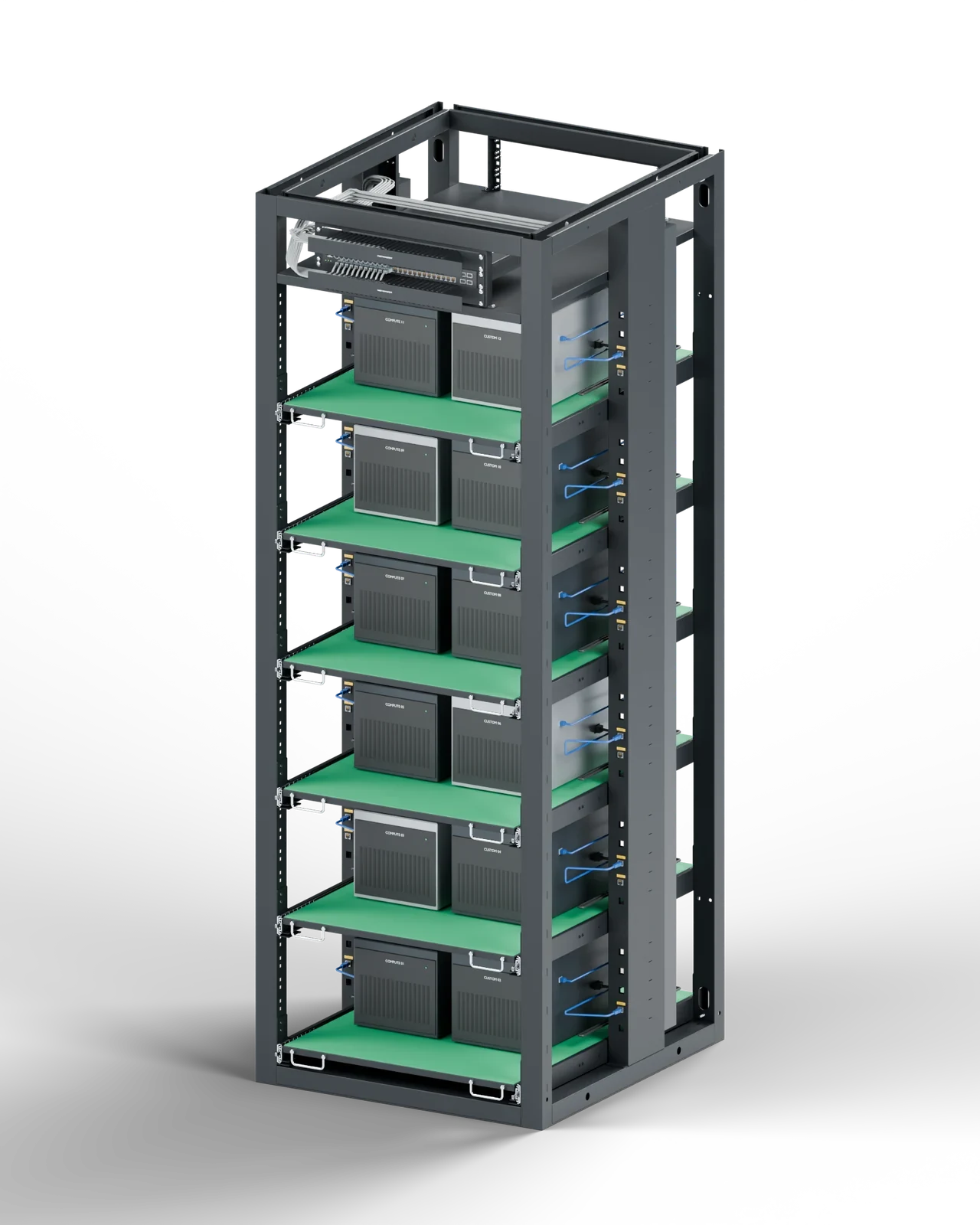
Organize one equipment area, or place racks side by side for more equipment positions and network points.
- Sliding shelves
- 6 shelves
- Illustrated network points
- 22 points
Rack fastening, network and power options are specified for the installation.
05 — SPECIFICATIONS
Plan the space. Define the configuration.
Start with equipment dimensions and service access. We will work with you on shelving, network points and power distribution.
| Single-rack dimensions | 822 × 900 × 2303 mmWidth × depth × height |
|---|---|
| Equipment | Servers, custom enclosures and non-rackmount equipmentConfigured to dimensions, weight, cooling and power requirements |
| Sliding shelves | 6 per rackSide-mounted telescopic rails. Travel confirmed with the rail configuration and installed equipment. |
| Service access | Shelves are pulled out for replacement, maintenance and repair, with network and power connections kept in placeWorking allowance is arranged behind the shelf side |
| Power | Power leads run from the rear PDU to the equipment on each shelfGB 2099 plug at the PDU, IEC C13 at the equipment; PDU model and outlet type selected for the project |
| Network equipment | Switch, upper and lower cable managers, side-mounted modules and direct module cablesConfigured per project |
| Deployment | Single rack / side-by-side racks |
Before we configure your racks
Which equipment suits SmartRack?
Servers, custom enclosures and equipment whose dimensions, interfaces or mounting do not suit a standard server rack. Shelf spacing, load and cooling are confirmed against the actual equipment.
How far does a shelf pull out?
The images and video show a presentation position, not a rated travel. Actual travel is defined with the rail specification, equipment weight and centre of gravity, cable allowance and rack anchoring.
Do cables have to be disconnected before pulling out a shelf?
Cable routing is designed so that network and power connections stay in place while the shelf moves. Whether equipment may stay powered during service depends on the equipment and the site procedure.
Is the Aruba switch included as standard?
Aruba 6200F is shown in this configuration example. The exact switch, port count and power options are selected for the project.
LET'S CONFIGURE YOUR WORKSPACE
Tell us what your equipment needs.
Equipment dimensions · rack count · network points · power requirements